Tuning beam through LEBT (to the Last Faraday Cup Before the Experiment)
1. Set the electrostatic benders according to the Source and Destination settings.
ITW/ITE to Yield *
- ILT:VB21 open
ITW/ITE to LEBT*
- ILT:VB21 closed
- ILE:B1 closed
- ILE:B4 closed
ITW/ITE to RFQ*
- ILT:VB21 closed
- ILE:B1 open
- IOS:B13 open
OLIS to LEBT
- IOS:B10 open
- ILE:B4 open
OLIS to RFQ
- IOS:B10 closed
- IOS:B13 closed
*CSB Operation
- CSB:B1 closed
- ILT:XCB7 polarity must be set for CSB
2. Load theory optics values (including quads and benders) from source to destination using the Beam Dynamics page.
Be sure to take special note of the quadrupole settings before and after electrostatic benders. Depending on the desired path of the beam these settings will change.
In some cases the beam dynamics expert will ask us to load a previous tune. It is a good idea to compare the quad / bender values with the theory numbers above. If large discrepancies are found it may be worth noting. Ensure that they are different "on purpose" and not because they were forgotten during the previous tuning exercise.
3. Set steering to zero effect.
For 1000V power supplies, set the common plate and all other plates to 500V.
4. Tuning.
Take note of the beam current at the source and methodically work from Faraday cup to Faraday cup , maximizing the transmission while ensuring that the beam profile looks "good" (see below) and is in the correct position (centered). We expect 95-100% transmission through LEBT (after IMS:FC34 or IOS:FC6 to the Faraday cup before the experiment).
What is a "good" beam profile (measured using RPMs and Harps)?
Shape -- The beam profiles should be roughly Gaussian. Double-peaks (Batman ears) are an indication that the upstream focusing is incorrect; a shoulder indicates that a combination of steering and focusing may be incorrect; a sharp drop on one side, or both sides, of the beam profile probably means that beam is being "cut" somewhere, maybe by slits or in a bender.
Size -- You've taken an RPM scan and you have Gaussian X and Y beam profiles at a location along the beamline. Now what? Should they be the same height (i.e. a circular beam), or not (i.e. more focused in X or Y)? To answer this you can use the 'MatLab Beam Envelopes' application (right click on the desktop).
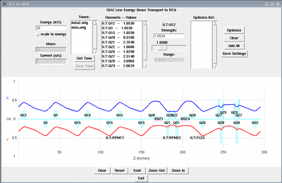
The picture below shows the Beam Envelope calculation from ILT:Q1 to the RFQ:
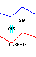
Below is a screengrab from the image above focused on ILT:RPM17. The RPM is located between two quads. At this location the X and Y profiles should be the same size. We expect a circular beamspot at ILT:RPM17, that is both X and Y profiles should be the same height.
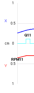
Below is another screengrab showing the beam envelopes at ILE2:RPM11. This is an example of a location where we expect the beam to be more focused in the X-plane.
Position -- If the position of the beam is incorrect, adjustments to steering or benders may be required. Ideally, we would like the beam to be centered in between 45 Deg benders (confirmed using RPMs). If all is well, minimal steering should be required to get the beam to fly to the next bender. If harsh steering is required in multiple locations there is a good chance that the beam is "zig-zagging" through the line. This is not desired, since we want the beam to travel through the center axis of the various quads. If beam is off-axis, focusing will be affected and the quad will also steer the beam.
To horizontally center the beam on the RPM in between benders try adjusting the first 45 Deg bender. Typically, no more than a 2-3% change should be required. With downstream steering set to zero effect, try making a small adjustment to the 2nd 45 Deg bender (once again, ~2-3% is probably okay) to maximize the signal on the first Faraday cup downstream of the bender. Confirm that the beam is centered on the RPM in the same (or closest upstream) diagnostics box as the cup. If it isn't, some combination of benders and steering will be required. It is difficult to write a procedure for this, but with experience you will get a feel for what "works" and what doesn't.
Vertical steering: As above, attempt to center beam on RPMs using the minimal amount of vertical steering.
Note: "Horizontal" above refers to the plane in which benders are working on the beam. In the vertical ILT section this can be confusing -- pay attention to the RPM Compare profile labels: "NorthSouth" or "EastWest".
Are the RPMs centered and aligned in the beamline?
In short, we don't know. A good method is to open a "benchmark" saved RPM tune and attempt to recreate the beam position. It should be noted that the green "reference" trace that opens by default may not be in the optimal position. These were chosen "back in the day" arbitrarily. In time we will replace the arbitrary traces with benchmark tune traces.
5. Document the tune! Once you are happy with your tune document it (RPMs, FCs) and post your results in the eLog.
